Monotron Eurorack Mod
More than six years after I bought my Korg Monotron, I decided to make a mod to put it in my Eurorack.

Monotron-Kills
This is something that has been already done before by other persons. A search shows the Pulp Logic kit and also some threads in MuffWiggler. However, I intentionally avoided looking at this pages since I wanted to figure it out by myself. I called my mod Monotron-Kills.
By looking at the schematics and making a few measurements I defined the necessary things to adapt it. Since the Monotron works in a low voltage my approach was to adapt the input and output voltages to support the plus minus twelve volts of the Eurorack.
The first step was to remove one capacitor of the Monotron in order to break the connection of the VCO to the VCF. In the picture you can see the cap I removed.
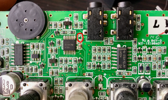
One capacitor removed to break VCO->VCF
I also removed the ‘standby/pitch/cuttoff’ switch in order to break the connections from the LFO to the VCF or VCO. I put in place a wire to keep the Monotron ON the whole time. I removed all the potentiometers in the board and also the volume control. Once all afore mentioned components were removed I soldered wires to get the following inputs/outputs:
- VCO output: the point is labeled on the PCB
- LFO output: labeled on the PCB
- VCF output: this one is taken from one of the pads of the volume control
- VCO Pitch: labeled on the PCB
- VCF Cutoff: labeled on the PCB
- Gate: labeled on the PCB
- VCF input: lower pad of the removed capacitor
Using these terminals is possible to get one VCO, VCF and LFO from the Monotron. The following image show the circuit I designed to adapt it.
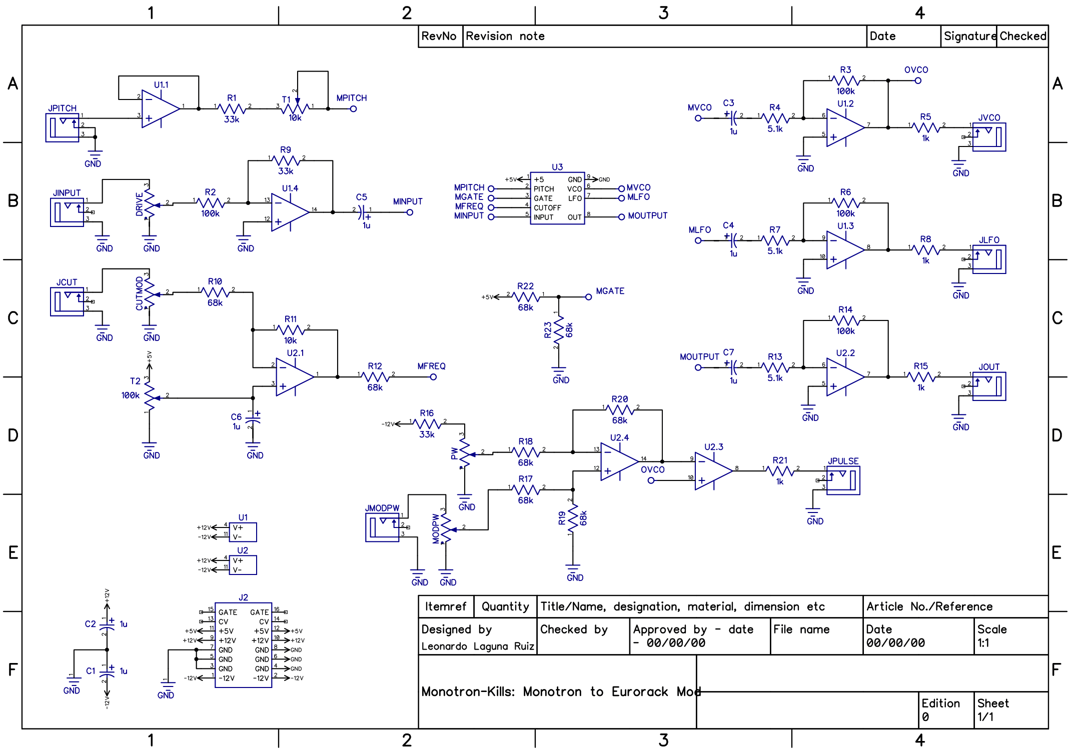
Schematic of the Eurorack adapter
Here you can get the PFD version of the schematic. In the schematic the component U3 represents the Monotron board.
Since the main circuit used 6 opamps and I had 8 available I decided to add PWM output from the VCO. I also added two jacks to add CV control to the PWM and the VCF.
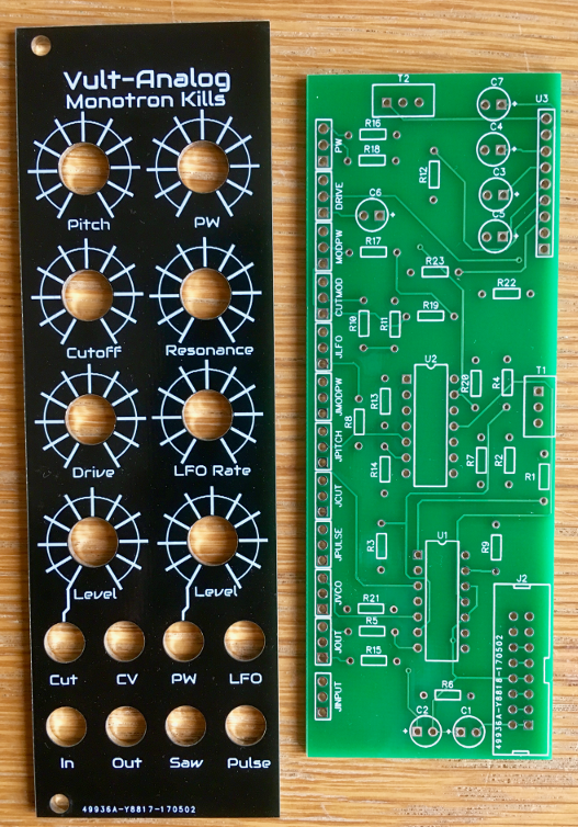
Panel and adapter board
Based on this schematic I designed a PCB which I intended to use just for testing purposes. But once I wired all and checked that everything worked I got lazy and didn’t tear apart the prototype. So I designed a panel to mount my ugly prototype.
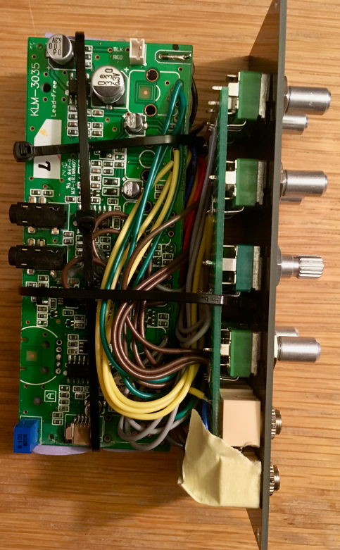
Prototype mounted to the panel (Monotron side)
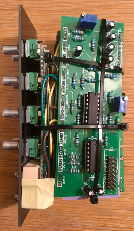
Prototype mounted to the panel (adapter side)
Once the Monotron-Kills is mounted you cannot see the mess that lies behind.

Monotron-Kills mounted
Here you can hear a demo of the module.
In retrospective, these are some of the things that can be improved:
- Desing a PCB to mount all pots and jacks. This PCB should make easy to mount the Monotron board and the adapter.
- This module is 8HP (~ 40 mm) and it has too many knobs and jacks. Making the panel 12HP or 14HP would have been better.
- The LFO output should not use decoupling capacitor since this capacitor destroys the signal for very low frequencies.
- The VCF output should have higher gain.