Steiner-Parker VCF
This is my version of a Steiner-Parker VCF for Eurorack format. This implementation is based on the design by Yves Usson (Yusynth).
If you don’t know the story. I’m trying to build my own Eurorack synthesizer… and by build I mean creating all the modules. Most of the modules (and synthesizers) that I have built are hand-soldered in perfboards. For this module, I wanted something more “professional” looking. That’s why I decided to design and manufacture the PCBs. In this case I used CircuitMaker.
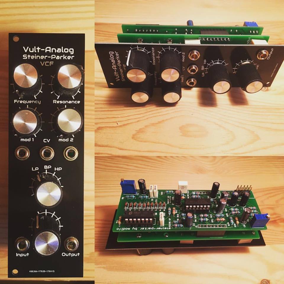
Vult-Analog Steiner-Parker VCF
You can find the original design here Yusynth
The module consist of three boards: a panel, a control board and the analog board. If you want to make your own, you can find my original design files here.
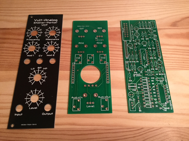
The three boards
But before making your own you have to be aware that this initial design is not perfect. So keep reading.
Building your own
This are the schematics of the filter:
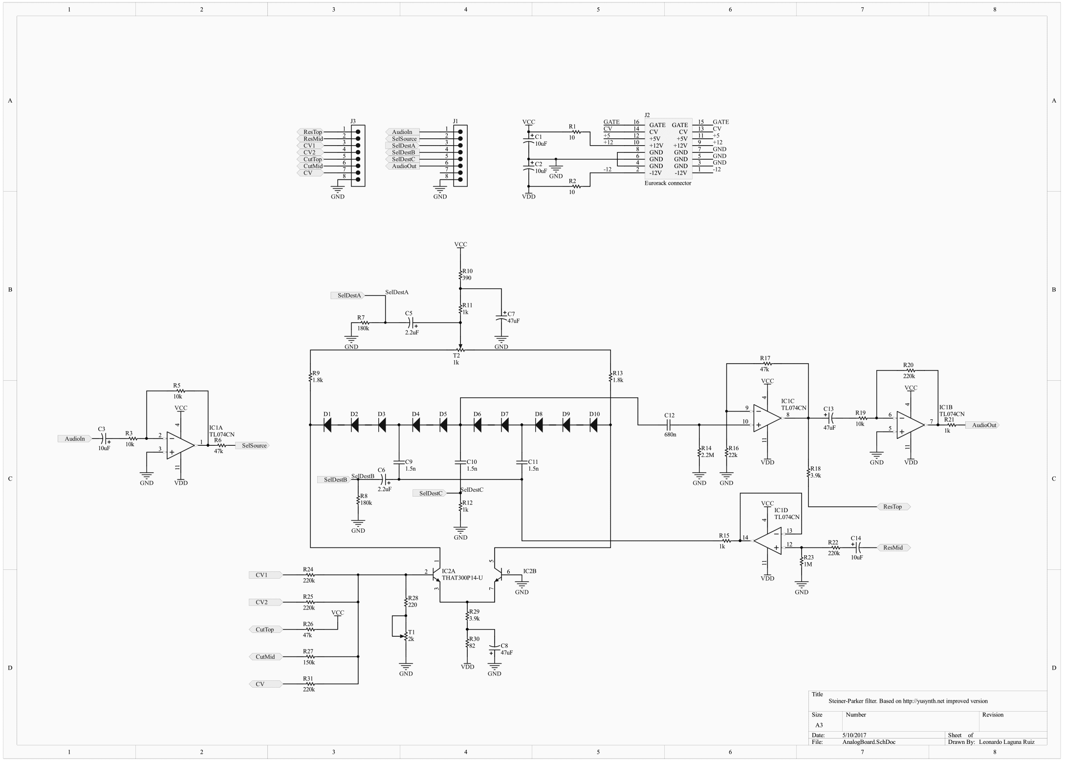
Steiner-Parker main board
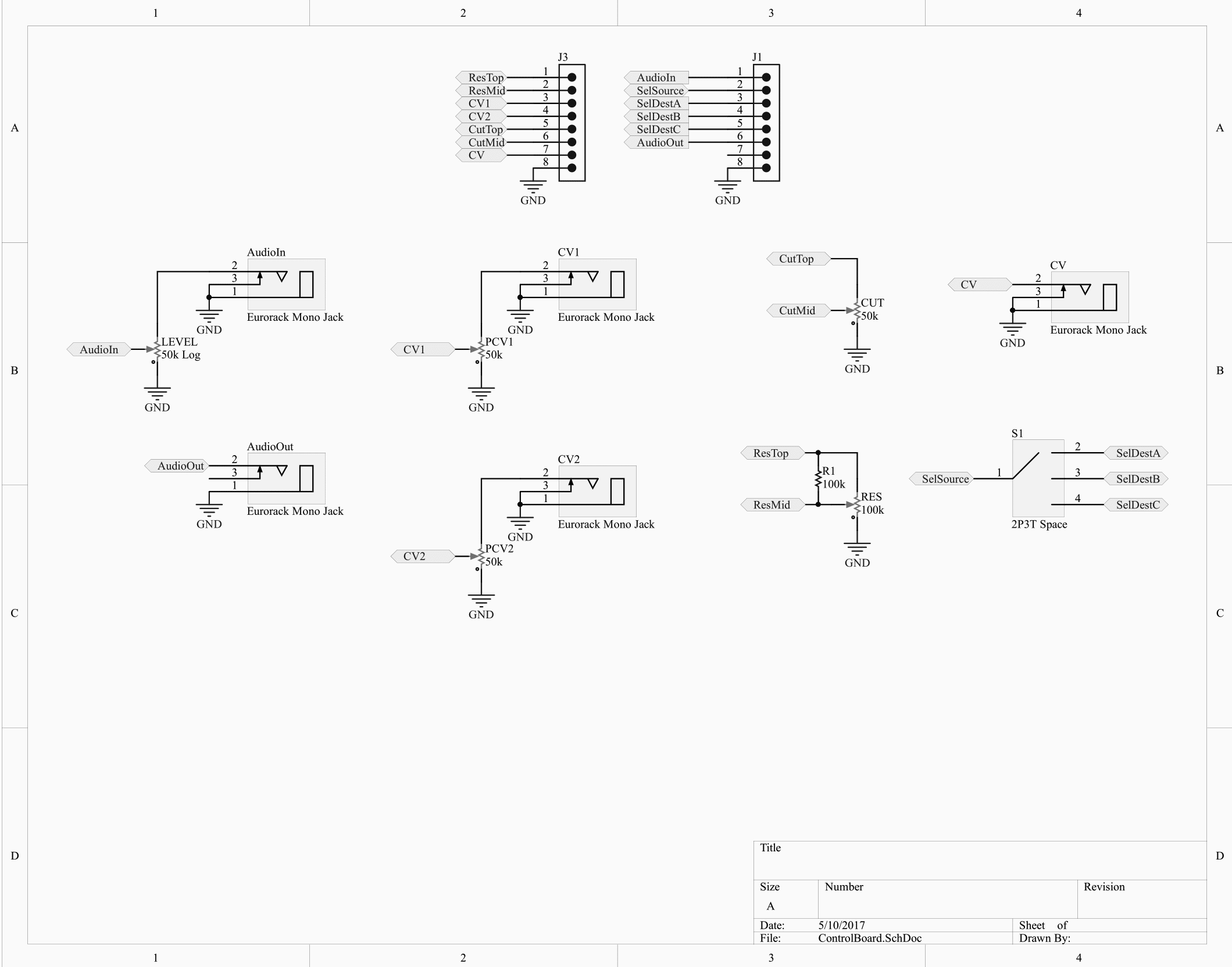
Steiner-Parker control board
These are the schematics in PDF format main, control.
Regarding the components, I got practically all of them from Musikding.
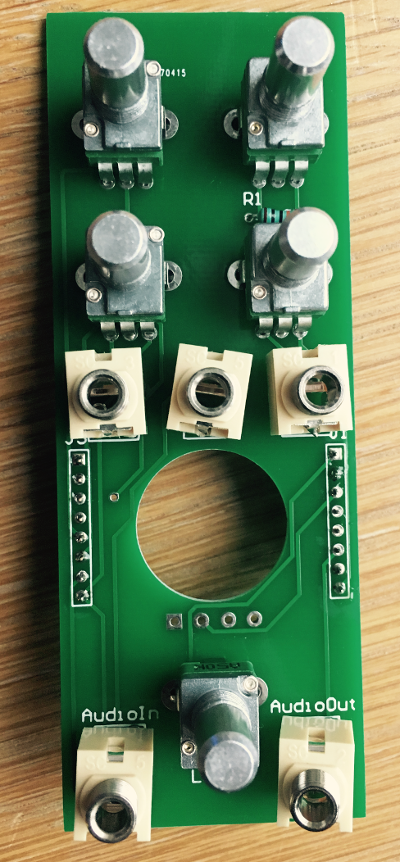
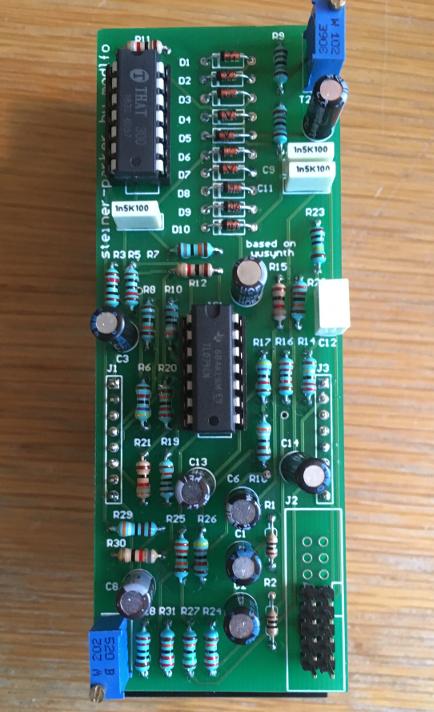
This filter uses a pair of matched transistors. Yves recommends BC547C or a 2SC1583. In my case I used a THAT300P14 which contains 4 transistors (two of them are unused). If you have a pair of matched transistors you can use them instead. As you can see in the picture below, the trimpots are precision trimpots.
Main board
One mistake that I made in the first (and only) batch of the board was an incorrect trace. The good thing is that it’s very easy to fix. I incorrectly connected the feedback of the resonance control to the wrong pin of the opamp. You can see the fix in the picture below.
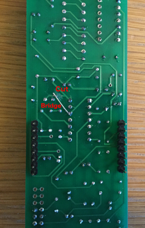
Fix for the first batch of boards
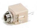
My second mistake was when buying the jacks. I designed the PCB for these jacks (Lumberg 1502 03), since I had a few of them:
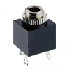
Matching jacks
But the ones I bought were:
Alternative jacks (requires some fixing)
Since the pins do not match I had to adapt them by cutting the original pins and soldering new pins that matched the originals.
One part that I didn’t have when designing the board was the filter mode selector. In the original design Yves uses 3P4T rotary switch. I was not sure that I could easily find it, therefore I made a big hole in the PCB and exposed the pins (one source and three destinations: LP, BP, HP). That way I could adapt any switch I could get. At the end I used a Mini rotary switch 2P3T from Musikding. Using this switch you can not have the all-pass mode of the filter.
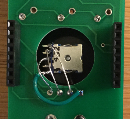
Connecting a 2P3T switch